3D Printing
ShieldBase™ — The Only Geometry Designed FOR 3D Printing
Protected contact zone, support-free printing, three tolerance variants. ShieldBase™ geometry is Hague-registered and patent pending.

Dental Technician & Inventor
Engineered From Scratch, Not Adapted
Every plaster-free system on the market started from the same place: an existing articulator base, modified to work with magnets instead of gypsum.
Those bases were never designed for printing. They were designed for plaster broad, flat surfaces meant to embed in plaster and hold under manual pressure. That's a sound design for the problem it was solving in 1985. It's the wrong starting point for a resin printer.
When you repurpose that geometry for magnetic mounting, the legacy problems come with it. Oversized footprints eat build plate space. Bulk that was harmless in plaster now forces awkward print orientations. Contact zones sit exposed where supports have to attach and every support scar in a mating surface is a fraction of a millimeter you didn't design and can't measure.
ShieldBase™ started from zero. Not "how do we adapt this to print," but "what geometry does a resin printer actually want to produce, and how do we build a transfer interface out of that?"
Every dimension in ShieldBase™ answers a printing question first and a mounting question second. That order matters. It's why the geometry is compact enough to sit clear of implant analogs, thin enough to print without supports where it counts, and shaped so the surfaces that determine position are never the surfaces the printer struggles with.
Anatomy of ShieldBase™
Four elements do the work. Each one exists to solve a specific additive-manufacturing failure mode.
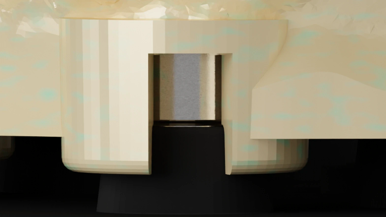
The two-step blind seat cavity. The magnet seat isn't a simple hole. It's a two-stage cavity: a wide mouth above, a narrower bore below. The mouth captures excess adhesive and acts as a self-centering chamfer. The bore holds the magnet at a controlled depth. The technician doesn't align anything by hand. The geometry does it.
The peripheral lip (≤0.7mm). A shallow horizontal overhang rings each seat. It's deliberately kept under 0.7mm, thin enough that a DLP or LCD printer reproduces it cleanly without local supports. Why does this matter? Because the alternative is putting a support directly on or beside the contact zone, then removing it, then polishing the scar. That's three opportunities to change a surface that defines position. The lip prints support-free, so the contact zone is never touched after the build.
The stand-off rim (2–3mm). Every resin printer over-exposes its first layers. That's not a defect, it's how adhesion to the build plate works. The problem is that over-exposed layers grow horizontally, and if your functional mating surface sits in that zone, your vertical fit is wrong before you've done anything else. The stand-off rim lifts the seating geometry 2–3mm clear of those foundation layers. Whatever happens in the first-layer zone stays in the first-layer zone.
Three XY-tolerance variants. In-plane build error is printer-specific and resin-specific. Rather than shipping a single hardware size and hoping, the CAD library offers three seat variants — tight, standard, loose, whose bore diameters differ by 0.07–0.15mm. The technician selects the fit in CAD, before the model is exported. A slip fit, a light press fit, or a firm press fit, chosen deliberately instead of discovered at the bench with a magnet that won't seat.
The plates themselves are manufactured in one nominal size. All the compensation lives in the file, where it costs nothing to change.
Why Flat Printing Matters
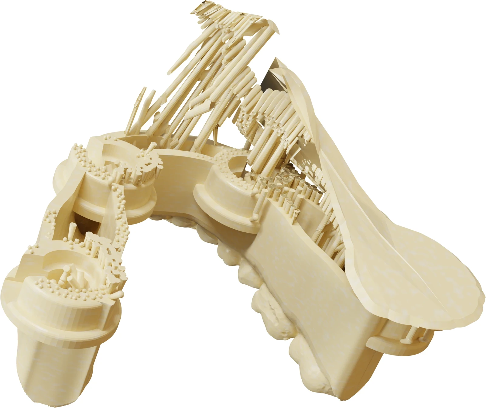
ShieldBase™ prints flat, directly on the build plate, or with standard supports placed under non-critical regions. No 45° orientation. No vertical nesting.
That single fact cascades:
Fewer layers. Flat orientation means less Z-axis travel per model, and less accumulated Z-axis error.
No supports in critical zones. Supports go where they don't matter. The contact geometry is never a support attachment point.
Maximum build plate capacity. Compact footprint, flat nesting — more models per print cycle.
Teeth printed horizontally. This is the one most people underestimate. Occlusal detail is captured best in the printer's highest-resolution plane. Print the arch on edge and you're resolving cusps and fissures along the axis where your printer is weakest.
Competitor geometries that force 45° orientation give up all four at once — longer builds, more supports, fewer models per plate, and softer occlusal detail. They do it to make a plaster-era base fit on a printer. ShieldBase™ never had that debt to pay.
Real IP, Not a Generic Shape
ShieldBase™ geometry is protected by a Hague design registration and by a pending international patent application covering the blind seat geometry, the peripheral lip, the stand-off rim, and the tolerance variant system.
This isn't a shape anyone can redraw over a weekend. The protected elements are the specific ones that make support-free flat printing possible while preserving a calibrated mating surface, which is precisely the combination competitors would need to replicate.
See how ShieldBase™ integrates with the full ZeroDrift™ protocol →